
|
Our design process
|
|
Mike trained as an aircraft structures design draftsman at British Aerospace in the UK. (Co-incidentally, this was around the same time that race car constructors were moving from space-frame chassis to aircraft-type riveted, aluminum alloy, monocoques. Although, motorsport wasn't behind aerospace for long...). BAe taught Mike 'old school' sheet metal fabrication techniques, including the practice of producing very accurate 'template' drawings of flat-developed sheet metal components. This skill has long been obviated by CAD.
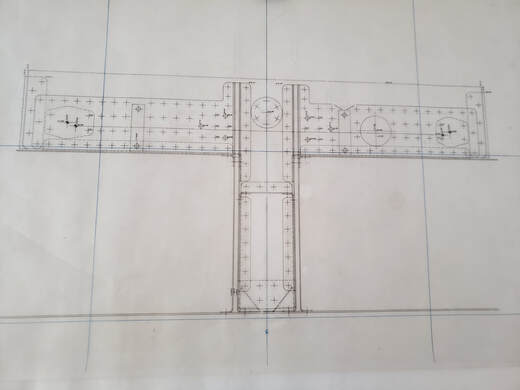
But what if you don't have CAD of the chassis with those tired, or bent, panels you need to replace? We use CAD (SolidWorks) for our designs. But we still find that sometimes we need a hand-drawn, template drawing to make sure those riveted panels go together properly like this one of an internal bulkhead assembly:
|
|
For other components, like castings, we use a 3D laser scanner. This scan produces a point cloud - literally millions of data points located on the surface of the original part. That electronic point cloud file is converted into an *.stl file, a tessalated surface comprised of thousands of triangles, (the points now connected together by lines). Then, these tessalated surfaces are used to re-create the original surface geometry of the casting in CAD.
